Welcome DIY fans!
This little page will be dedicated to my DIY build of a small Champ Amp Clone build... sort of.
This amp was a long time coming. I always feel that I'm about a year behind in my ambitions, but that's a story for another forum.
Anyway, I finally decided on a Champ-based build just to keep things simple and to stack the odds in my corner. The second objective was to complete this build as cheaply as possible. I'm not cheap, I just don't like wasting perfectly good beer money on pure folly.
With these two objectives finally laid out, the build started with pawing through my junkbox(es). The junk boxes offered up several good looking specimens of transformers. A few looked pretty obviously like power transformers, and the remaining few were either output trannys or maybe inductors.
Hmmm.
I decided to start at the beginning- the power tranny. I picked one randomly from the pile and made note of the color and number of wires sticking out of it. My next move was to consult the Great and Powerful Oz, er, I mean Google. There is a lot of good (and bad) information out on the web. I managed to find some of the good and was able to get a rough idea about my poor pile of power transformers.
Here's a link or two for some of the more standard color codes.
Using these and other diagrams and information, I started sorting through the trannys. I temporarily soldered an electrical plug to what I determined (guessed) what was the primary side. Turns out it was indeed the black wires. I then connected the plug into my trusty variac, aka, a variable transformer. I then applied a small, known voltage to the transformers primary and simply multiplied to determine what the transformers actual full-voltage outputs would be. Example; I first measured the voltage at my wall outlet. Let's say it was 120vac using my digital multimeter. Next, I plugged in the variac and set the output to 12vac, again, using my digital multimeter. Now I know that if I put that 12vac through the transformer, that I can just multiply what appears on the secondaries by ten to realize what my tranny is capable of in output.
Simple enough, right?
According to my calculations, I had a tranny that was giving me around 250v at the secondaries and a 6.5v tap for the heaters. with no 5v rectifier tap.
Hmmm. Seems to me that those voltages were close enough to run some tubes ;-)
Alright, so on I went!
Initial layout of components.
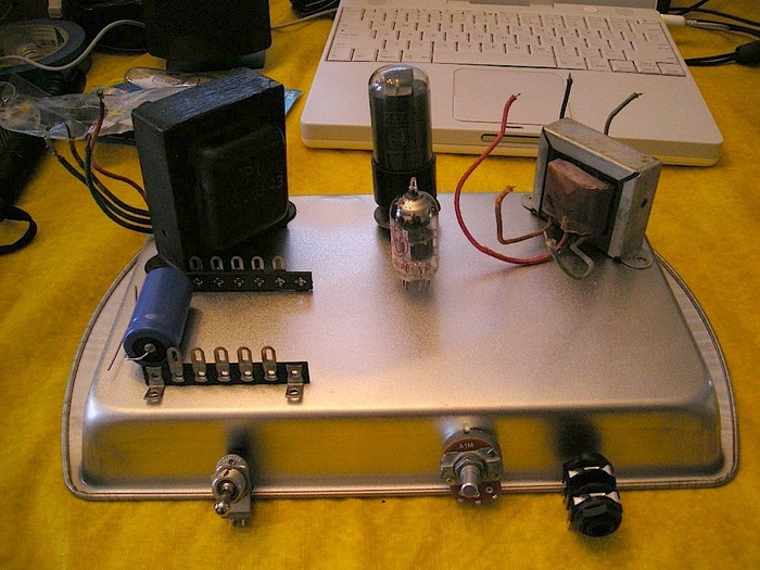
OK, so I more or less roughed out where the components would go. My next step was to start finalizing things with my layout drawing.

Remember, I am basically following a Champ 5F1 schematic. The biggest change to it that I did was to make it a solid state rectifier instead of tube. I used a bridge rectifier because it was cheaper and way more simple. Remember, my junkbox tranny didn't have a 5 volt tap.
You can see in my drawing how I placed the terminal strips and the trannies. Notice that I artfully arranged the trannies on an angle? It looks cool AND they are still facing each other at 90 degrees ;-)
Also evident in my drawing is my attempt to keep the power supply and the input/amplifier section separated.
Oh- before I forget, I got the terminal strips, tube sockets and other components from The Tube Depot! Click on their DIY page.
Oh, and another thing; here's a good book, Inside Tube Amps, by Dan Torres. I know a lot of people knock this book and I can understand that, a little. It can be a tough book to follow. He kind of jumps around a bit and assumes some previous knowledge of electronics on the reader's part, but of ALL of the books and pages I have read on the subject, this is the one that, in the end, explains things the most clearly. This book alone won't get you there, but reading this book will help to get you there faster... and on a solid foundation. I read this book at least six times and must have twenty bookmarks in it! They want $45 for it. That's kinda steep, but I gotta tell ya, after reading it, I can say it was worth it. Maybe you can find it used...?
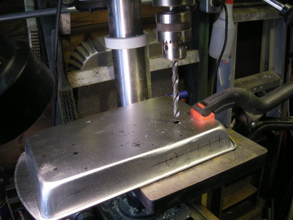
So the next step, after I did my drawings, was to drill out my "chassis." Being a cheap bastard, I wasn't gonna spend $100+ dollars on a nice, predrilled, purpose built chassis. Oh no. This is to be a junkbox build as much as possible. To save a ton of money, I used a cheap, steel brownie pan as my chassis.
My thoughts on my chassis choice; It was cheap, and because I made some mistakes when drilling it out, I'm glad I didn't spend a lot. Electrically, it works just fine. The cons are that it's flimsy. And it could have been a tad deeper- I had some trouble mounting the pots and stuff without touching the chassis or sticking out of the bottom.
Bottom line on the chassis; Cheap. Good for experiments or a cheap-ass build like this. If you want to gig out with it, build or buy a more substantial chassis.
Here's a pic of me drilling out the chassis. You can see in the pic how flimsy it was (slight bend/dent in the front. It got worse.)
Made life a bit difficult.
Before I dilled, I drew with pencil, the location of all of the holes and components such as pots, terminal stips, transformers, etc. You can see it in the picture below.
Email me (guy@almirasound.com) to get on a blog update email list.
Last update 5/20/11. To be continued with pictures and schematics.....